Engineering
\ Metal Flow Simulation
3D Forging
Processes
Heat Transfer Process – HT
Knock Down Process – KD
Second Die Process – SD
Final Die Process – FD
\ Simulation
Casting and Forging
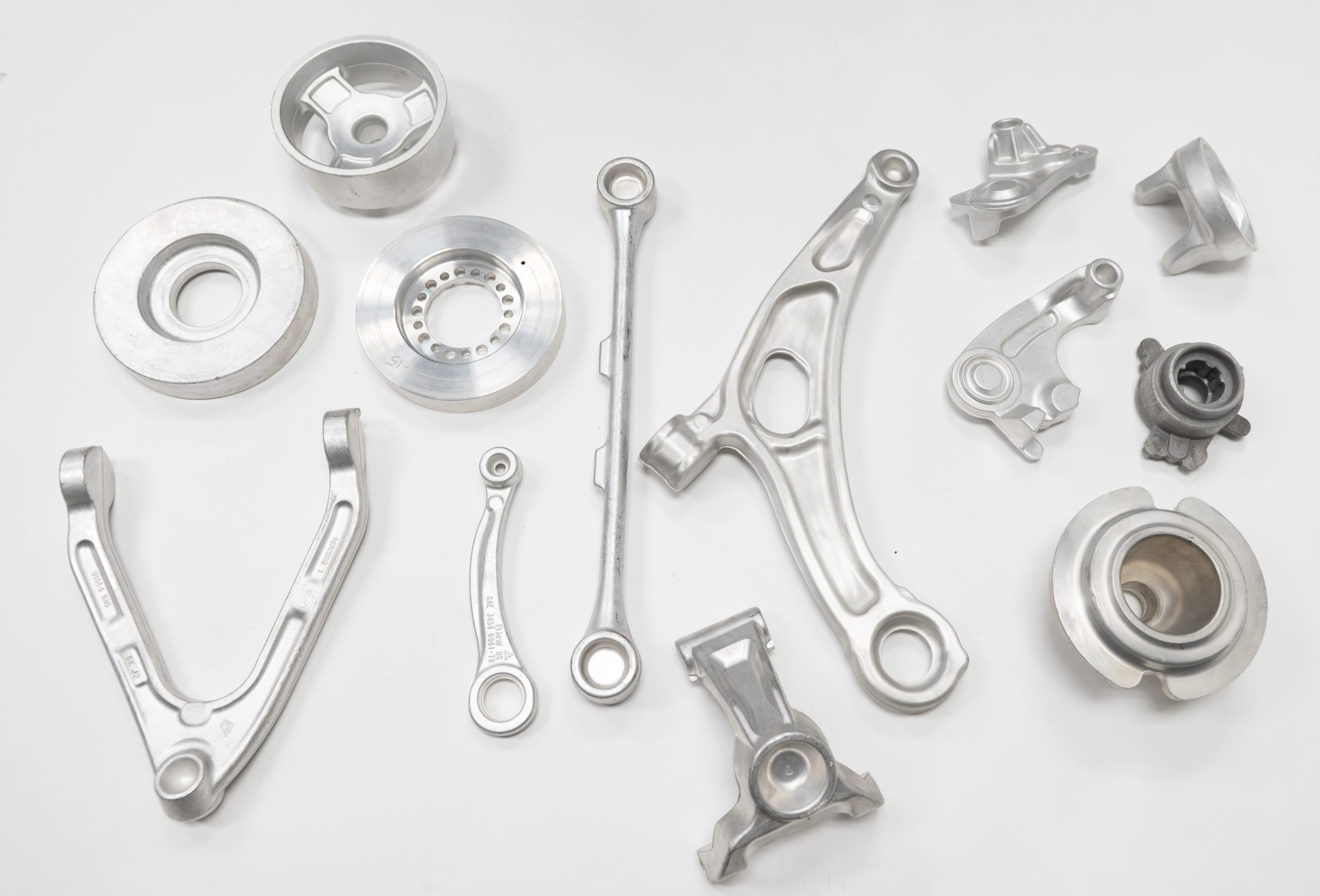
All developments go through casting and forging simulation as part of the process to determine the feasibility of the parts designed and ensure the expected level of quality.
Advantages of Forging Simulation
- Reduces the development time for a part.
- Prevents numerous tooling modifications by producing defect-free parts from the first strike.
- Defines the type of press to use.
- Optimizes the lifespan of forging tools
Advantages of Casting Simulation
- Reduces the development time for a part.
- Prevents numerous tooling modifications by producing defect-free parts from the first casting.
- Determines the process parameters without tests.
\ Mold Flow Simulation
Plastic Injection Molding
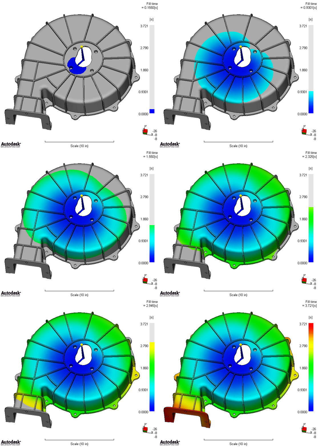
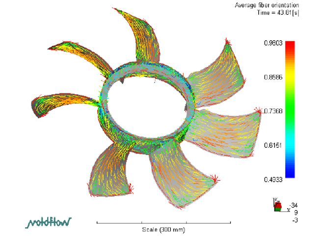
With our simulation capabilities, our plastic-injection molding plants can effectively analyze dimensions like time, pressure, and temperature. These will all help to increase structural integrity, wear resistance, airflow, balance, and more depending on application.
\ Case Study
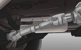
Exceeding Customer Requests – Re-engineered Prop Shaft (1420)
A large OEM approached Angstrom seeking a higher torque rating and improved performance for their prop shaft. To accomplish this goal, Angstrom first investigated processes that would improve the part performance without re-designing any components, however, none of these solutions were sufficient to meet the customer requirements while remaining cost competitive.
The next phase began with the engineering process, creating a concept design. After deciding that the optimal route would be to create a new joint, the engineering team created CAD models to improve the function and performance of the part from the ground up. Throughout the process, constant and timely communication with the customer was critical to make sure that all requirements were met or exceeded and any questions that arose during the process could be quickly and effectively addressed.
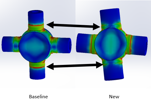
After the concept phase, the team started using comparative simulations to identify the performance improvements in the new part. As depicted in the simulations of the part in Figure 2, the original part (left) shows a much higher risk of part failure due to the stress loads. This is significantly reduced in our simulation model (right). Upon further analysis, Angstrom found that it was able to achieve an approximate 54% stress reduction, resulting in a stronger part that is less likely to fail given the new customer requirements.
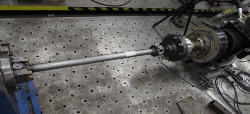
After all simulations were completed and the new design developed, a proposal was submitted to the customer which included all the improvements made to the components along with the cost and timing to complete the project. The last phase in the engineering process included a final design freeze and the creation of a prototype to bench test and validate the design.
The initial targets were to improve the existing joint’s torque rating to 5000Nm; however, the results came back nearly 10% stronger than target. With Angstrom’s engineering and manufacturing expertise combined, our team was able to significantly improve performance and eliminate the existing failure mode. The customer was so satisfied that the new joint will be implemented on a future program as well as the current manufactured product!
